
Page 705 - Mastik®
P. 705
Selection criteria for self-tapping Design guideline
®
Ensat inserts
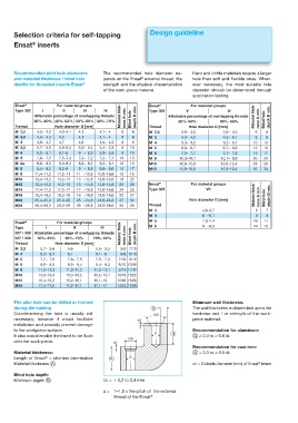
Recommended pilot hole diameters The recommended hole diameter de- Hard and brittle materials require a larger
®
and material thickness / blind hole pends on the Ensat external thread, the hole than soft and flexible ones. When-
depths for threaded inserts Ensat ® strength and the physical characteristics ever necessary, the most suitable hole
of the work-piece material. diameter should be determined through
application testing.
Ensat ® For material groups Ensat ® For material groups
Type 302 I II III IV Type 309 V VI
Attainable percentage of overlapping threads Material thick- ness A min. depth B min. Attainable percentage of overlapping threads Material thick- ness A min. depth B min.
30%–40% 40%–50% 50%–60% 60%–70% Blind hole 85%–90% 90%–95% Blind hole
Thread Hole diameter D [mm] Thread Hole diameter D [mm]
M 2,5 4,3– 4,2 4,2–4,1 4,1 4,1– 4 6 8 M 2,5 3,8– 3,6 3,6– 3,5 6 8
M 2,6 4,3– 4,2 4,2 4,1 4,1– 4 6 8 M 3 4,3– 4,2 4,2– 4,1 6 8
M 3 4,8– 4,7 4,7 4,6 4,6– 4,5 6 8 M 4 5,3– 5,2 5,2– 5,1 10 13
M 3,5 5,7– 5,6 5,6–5,5 5,5– 5,4 5,4– 5,3 8 10 M 5 6,9– 6,7 6,7– 6,6 12 15
M 4 6,2– 6,1 6,1–6 6 – 5,9 5,9– 5,8 8 10 M 6 7,9– 7,7 7,7– 7,6 14 17
M 5 7,6– 7,5 7,5–7,3 7,3– 7,2 7,2– 7,1 10 13 M 8 10,3–10,1 10,1– 9,9 20 23
M 6a 8,6– 8,5 8,5–8,3 8,3– 8,2 8,2– 8,1 12 15 M10 12,8–12,6 12,6–12,4 23 26
M 6 9,4– 9,2 9,2–9 9 – 8,8 8,8– 8,6 14 17 M12 15,8–15,6 15,6–15,4 26 30
M 8 11,4–11,2 11,2–11 11 –10,8 10,8–10,6 15 18
M10 13,4–13,2 13,2–13 13 –12,8 12,8–12,6 18 22
M12 15,4–15,2 15,2–15 15 –14,8 14,8–14,6 22 26 Ensat ® For material groups
M14 17,4–17,2 17,2–17 17 –16,8 16,8–16,6 24 28 Type 305 VII
M16 19,4–19,2 19,2–19 19 –18,8 18,8–18,6 22 27 Material thick- ness A min. depth B min.
M20 25,4–25,2 25,2–25 25 –24,8 24,8–24,6 27 32 Hole diameter D [mm] Blind hole
M24 29,4–29,2 29,2–29 29 –28,8 28,8–28,6 30 36 Thread
M 3 4,6–4,7 6 7
M 4 6 –6,1 8 9
M 5 7,3–7,4 10 11
Ensat ® For material groups
Type I II III M 6 9 –9,2 14 15
307 / 308 Attainable percentage of overlapping threads Material thick- ness A min. depth B min.
337 / 338 50%–60% 60%–70% 70%–80% Blind hole
Thread Hole diameter D [mm]
M 3,5 5,7– 5,6 5,6 5,6– 5,5 5/8 7/10
M 4 6,2– 6,1 6,1 6,1– 6 6/8 8/10
M 5 7,7– 7,6 7,6– 7,5 7,5– 7,4 7/10 9/13
M 6 9,6– 9,5 9,5– 9,4 9,4– 9,3 8/12 10/15
M 8 11,5–11,3 11,3–11,2 11,2–11,1 9/14 11/17
M10 13,5–13,3 13,3–13,2 13,2–13,1 10/18 13/22
M12 15,4–15,2 15,2–15,1 15,1–15 12/22 15/26
M14 17,4–17,2 17,2–17,1 17,1–17 14/24 17/28
The pilot hole can be drilled or formed Minimum wall thickness:
during die-casting The wall thickness is dependant upon the
Countersinking the hole is usually not 60° hardness and / or strength of the work-
necessary; however it would facilitate a piece material.
installation and possibly prevent damage
to the workpiece surface. Recommendation for aluminum:
D
It also would enable the insert to be flush S ≥ 0.3 to ≥ 0.6 d2
DA
with the work-piece. a
Recommendation for cast iron:
Material thickness: S ≥ 0.3 to ≥ 0.5 d2
Length of Ensat = shortest permissible D
®
®
Material thickness A d2 = Outside diameter (mm) of Ensat insert
Blind hole depth:
Minimum depth B DA = + 0,2 to 0,4 mm
a = 1–1,5 x the pitch of the external
thread of the Ensat ®