
Page 700 - Mastik®
P. 700
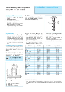
Direct assembly in thermoplastics                     Construction recommendations
                       ®
            using PT / eco-syn screws


                                                     ®
                          ®
            Advantages of PT  screws / eco-syn  The PT / eco-syn screws have been
            r  -PX  ESJWJOH  UPSRVF   IJHI  TUSJQQJOH   used successfully for years. PT  screws
                                                                        ®
              torque                           have the necessary features to enable a
            r  )JHI BTTFNCMZ TBGFUZ            secure joint in thermoplastics.
            r  &YDFMMFOU WJCSBUJPO SFTJTUBODF
            r  -PX CVSTUJOH UFOEFODZ
                                                                                          P                 30°
            r  /P FYDFTTJWF KPJOU SFMBYBUJPO UIFSFGPSF
              plastic components do not shift
            r  Cost-effective fastener for direct fas-
              tening in thermoplastics


            Design guidelines                  r  %P OPU VTF DPVOUFSTVOL TDSFXT  5IF   torque to be bigger than the under-
            r  'PS  GBTUFOJOH  QMBTUJD  QBSUT   TQFDJGZ  B   90° head angle not only results in axial   head friction torque. Such a joint
              large head diameter (BN 20040). This   forces but also radial forces, hence   would be unsafe.
              increases friction under the head,   causing greater joint relaxation in   r  4IFBS GPSDFT TIPVME CF BCTPSCFE CZ
              making a safer joint. Also a larger head   parts with narrow edge margins. The   form-fitting components.
              reduces the surface pressure which   preload would be unsafe.        r  'VSOJTI UIF QJMPU IPMF FOUSBODF XJUI B
              in turn minimizes joint relaxation and   r  "WPJE FMPOHBUFE IPMFT JO QMBTUJD QBSUT    counterbore (avoids stress cracking)
              ultimately increases the residual clamp   as they would create a small bear-
              load.                              ing area, possibly causing the driving

                           ®
            Boss design for PT / eco-syn screws      Material         hole Ø d       external Ø D   length of thread
            An optimum boss design that will hold                                                    engagement te
            up in the application, requires the boss   ABS / PC blend  0,80 x d1      2,00 x d1        2,00 x d1
            geometry to be adjusted to the different   ASA           0,78 x d1        2,00 x d1        2,00 x d1
            plastics.                           PA 4.6               0,73 x d1        1,85 x d1        1,80 x d1
                                                PA 4.6 - GF 30       0,78 x d1        1,85 x d1        1,80 x d1
            The details shown here are based on   PA 6               0,75 x d1        1,85 x d1        1,70 x d1
            laboratory testing. Some changes may   PA 6 - GF 30      0,80 x d1        2,00 x d1        1,90 x d1
            be needed to fit your application.   PA 6.6              0,75 x d1        1,85 x d1        1,70 x d1
                                                PA 6.6 - GF 30       0,82 x d1        2,00 x d1        1,80 x d1
                   We recommend that users      PBT                  0,75 x d1        1,85 x d1        1,70 x d1
                   conduct application testing   PBT - GF 30         0,80 x d1        1,80 x d1        1,70 x d1
                                                PC                                                           1)
                   and joint analyses.                               0,85 x d1        2,50 x d1        2,20 x d1
                                                PC - GF 30           0,85 x d1        2,20 x d1        2,00 x d1 1)
                                                PE (soft)            0,70 x d1        2,00 x d1        2,00 x d1
                                                PE (hard)            0,75 x d1        1,80 x d1        1,80 x d1
                          D
                                                PET
                        Pressure                                     0,75 x d1        1,85 x d1        1,70 x d1
                                 0,3–0,5 x d 1  PMMA                 0,85 x d1        2,00 x d1        2,00 x d1
                        relief hole             PET - GF 30          0,80 x d1        1,80 x d1        1,70 x d1
                       de = 1,05 x d 1          POM                  0,75 x d1        1,95 x d1        2,00 x d1
                                                PP                   0,70 x d1        2,00 x d1        2,00 x d1
                                                PP - TV 20           0,72 x d1        2,00 x d1        2,00 x d1 1)
              L = 1,1–1,2 x te  =  d  t e       PS                   0,85 x d1        2,50 x d1        2,20 x d1
                                                PPO
                   =
                                                                     0,80 x d1
                                                                                      2,00 x d1
                                                                                                       2,00 x d1
                                                PVC (hard)
                                                                     0,80 x d1
                                                                                      2,00 x d1
                                                                                                       2,00 x d1
                                                SAN
                                         s                           0,77 x d1        2,00 x d1        1,90 x d1
              Taper 0,5–1,0°
                                               d1 = nominal thread diameter Ø
            D outside Ø                        1)   Since these materials are more susceptible to stress cracking, it is highly recommended to carry
            d  pilot holed Ø                     out application testing. Also, a counterbore (relief bore) is strongly recommended to minimize stress
            t e  length of thread engagement     risers.
            d e edge relief
            d 1  nominal Ø of the screw