
Page 699 - Mastik®
P. 699
Direct assembly in thermoplastics Construction recommendations
using Delta PT screws
®
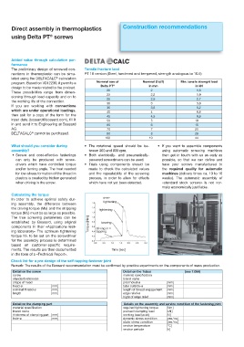
Added value through calculation per-
formance
The preliminary design of screwed con- Tensile fracture laod
nections in thermoplastic can be simu- PT 10 version (Steel, hardened and tempered, strength analogous to 10.9)
®
lated using the DELTACALC calculation
program. Based on VDI 2230, it permits a Nominal size of Nominal Ø (d1) Min. tensile strenght load
Delta PT ® in mm in kN
design to be made related to the preload.
20 2 1,6
These possibilities range from dimen-
22 2,2 1,9
sioning through load capacity and on to 25 2,5 2,7
the working life of the connection.
30 3 3,8
If you are working with connections
35 3,5 5,2
which are under operational loadings,
40 4 6,8
then ask for a copy of the form for the 45 4,5 8,6
input data (bossard@bossard.com), fill it 50 5 10
in and send it to Engineering at Bossard 60 6 15
AG. 70 7 21
®
DELTACALC cannot be purchased. 80 8 28
100 10 44
What should you consider during r 5IF SPUBUJPOBM TQFFE TIPVME CF CF r *G ZPV XBOU UP BTTFNCMF DPNQPOFOUT
assembly? tween 300 and 800 rpm. using automatic screwing machines
r 4FDVSF BOE DPTU FGGFDUJWF GBTUFOJOHT r #PUI FMFDUSJDBMMZ BOE QOFVNBUJDBMMZ then get in touch with us as early as
can only be produced with screw- powered screwdrivers can be used. possible, so that we can define and
drivers which have controlled torque r 5SJBMT VTJOH DPNQPOFOUT TIPVME CF have your screws manufactured to
and/or turning angle. The heat needed made to check the calculated values the required quality for automatic
for low-stress formation of the thread in and the repeatability of the screwing machines (delivery times ca. 10 to 16
plastics is created by friction generated process, in order to allow for effects weeks). The automatic assembly of
when driving in the screw. which have not yet been detected. «standard stock screws» is not nor-
mally economically justifiable.
Calculating the torque
over-
In order to achieve optimal safety dur-
tightening
ing assembly, the difference between
the driving torque (Me) and the stripping
tightening
torque (Mü) must be as large as possible.
The true screwing parameters can be
established by Bossard, using original Torque [Nm] bearing
components in their «Applications test- driving in =
ing laboratory» The optimum tightening tapping
torque MA to be set on the screwdriver
for the assembly process is determined
based on customer-specific require-
ments. The results are then documented Time [sec]
in the form of a «Technical Report».
Check list for a pre-design of the self-tapping fastener joint
Remark: The results of the Bossard recommendation must be confirmed by practice experiments on the components of mass production.
Detail on the screw Detail on the Tubus (see T.056)
screw material specification
standard reference brand name
shape of head pilot holed-ø [ mm ]
head-ø [ mm ] tube outside-ø [ mm ]
nominal thread-ø [ mm ] length of thread engagement [ mm ]
length [ mm ] edge relief-ø [ mm ]
hight of edge relief [ mm ]
Detail on the clamping part Details on the assembly and service condition of the fastening joint
material specification required tightening torque [ Nm ]
brand name preload / clamping load [ kN ]
thickness of clamping part [ mm ] working load (axial) [ N ]
hole-ø [ mm ] dynamic stress condition [ yes / no ]
static stress condition [ yes / no ]
service temperature [ °C ]
service periode [ h ]