
Page 696 - Mastik®
P. 696
Direct assembly into metals using Construction recommendations
thread forming screws
according to DIN 7500
What should be considered in the de- r /P PUIFS TBGFUZ GFBUVSFT TVDI BT SF systems integrated into the surface
sign and construction processes? taining rings) are necessary. Resis- protection and/or an additional lubri-
r 5ISFBE GPSNJOH TDSFXT UP %*/ tance to vibration is provided by the cant can be used.
(trilobular) produce a chip-free, gauge- thread friction. r 5IFSF JT B SJTL PG GBJMVSF EVF UP IZESP
correct metric internal thread. r 5IFZ DBO CF SF VTFE m UJNFT gen embrittlement for thread-form-
r 5IF TDSFXT BSF IFBU USFBUFE UP HJWF B r 'PS UIJO TIFFUT UIF VTF PG QVODI ing screws with galvanic coatings.
2
tensile strength in use of ca. 800 N/mm . holes can help improve the mechani- A treatment must be carried out ac-
r *U JT QPTTJCMF UP GPSN UISFBET JO EVDUJMF cal properties of the fastening. cording to ISO 4042 to reduce the
metals such as steel, non-ferrous met- r *U JT SFDPNNFOEFE UIBU QSFMJNJOBSZ USJ risk of hydrogen embrittlement. High-
als and light metals up to ca. 140–160 als be made for «laser-bored» holes strength screws with property classes
HV. (the cut surfaces may be to hard.) 8.8 and higher must not be replaced
r 5ISFBE GPSNJOH JT OPU TVJUBCMF GPS CSJU r 1SFMJNJOBSZ USJBMT TIPVME CF NBEF GPS by case-hardened thread-forming
tle metals such as grey cast iron. critical applications. Get in touch with screws without an adequate examina-
r 5ISFBE GPSNJOH TDSFXT NBEF GSPN Bossard Engineering as early as pos- tion.
A2 stainless steel can only safely be sible in the development stage of your Functionally appropriate design of
screwed into light metals. In doing product. components and selection of the cor-
this the size of the pilot holes must r 'PS UIF GVODUJPOBM GVMGJMMNFOU PG B rect type of fastening element are
be 5% larger than the values in the thread-forming screw a suitable lubri- essential requirements for a secure
table. cation should be applied. Lubrication screw connection.
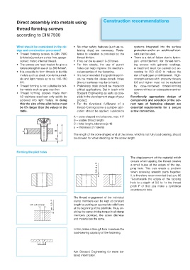
A = cone-shaped end of screw, max. 4 P
B = usable thread length
C = total length, tolerance js 16
s = thickness of material
s B
C
The length of the cone-shaped end of the screw, which is not fully load-bearing, should
A be allowed for when deciding on the screw length.
Forming the pilot holes
The displacement of the material which
occurs when tapping the thread creates
0,5–1 x P a small bulge at the edges of the tap-
ping hole. This can create a problem
when screwing smooth parts together.
It is therefore recommended that you 90
°Countersink the edges of the tapping
hole to a depth of 0,5 to 1x the thread
pitch P or that you make a cylindrical
countersunk hole.
The thread engagement of the individual
1,05 x Ø-nominal min. 0,5 x P clamp members can be kept at constant
length by putting an appropriate relief bore
at the beginning of the pilot hole. Thus, en-
abling the same driving torque in all clamp
members provided, the screw diameter
and material are the same.
In thin plates a through hole increases the
load-bearing capacity of the fastening.
Ask Bossard Engineering for more de-
tailed information.