
Page 701 - Mastik®
P. 701
Direct assembly in thermoplastics Construction recommendations
®
using PT / eco-syn screws
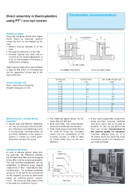
Changes of shape
Occur for the given shrink hole shape, D counterbore D
shrink marks or extended injection
cycles; the form can be changed as fol-
lows:
r 3FEVDF FYUFSOBM EJBNFUFS % PG UIF ll s 2 /3 s
tube. d
r *ODSFBTF UIF EJBNFUFS E PG UIF IPMF ll
r *ODSFBTF UBQQJOH IPMF EFQUI BOE TP
length of screw thread engagement, in s s
order to compensate for the losses in
resistance to stripping.
shrink marks
Select tapping holes which are sufficient-
ly deep so that under no circumstances unsuitable tube shape improved tube shape
can the assembled screws rest in the
base of the hole.
Nominal size Nominal Ø (d1) Min. tensile strength load
PT ® in mm in kN
Tensile strength load
K 18 1,8 1,1
Steel, hardened and tempered,
K 20 2 1,3
strength analogous to 10.9
K 22 2,2 1,6
K 25 2,5 2
K 30 3 2,7
K 35 3,5 3,6
K 40 4 4,6
K 50 5 7
K 60 6 9,8
K 70 7 13
K 80 8 16
K100 10 25
What should you consider during r 5IF SPUBUJPOBM TQFFE TIPVME MJF CF r *G ZPV XBOU UP BTTFNCMF DPNQPOFOUT
assembly? tween 300 and 800 rpm. using automatic screwing machines
r 4FDVSF BOE DPTU FGGFDUJWF GBTUFOJOHT r #PUI FMFDUSJDBMMZ BOE QOFVNBUJDBMMZ then get in touch with us as early as
can only be produced with screwdriv- powered screwdrivers can be used. possible, so that we can define and
ers which have controlled torque and/ r 5SJBMT NBEF VTJOH DPNQPOFOUT TIPVME have your screws manufactured to
or turning angle. The heat needed for be made to check the calculated the required quality for automatic
low-stress formation of the thread in values and the repeatability of the machines. (delivery times ca. 10 to
plastics is created by friction gener- screwing process, in order to allow 16 weeks). Automatic assembly using
ated when driving in the screw. for effects which have not yet been screws from stock is not normally eco-
detected. nomically justifiable.
Calculating the torque
In order to achieve optimal safety dur- over-
tightening
ing assembly, the difference between
the driving torque (Me) and the stripping tightening
torque (Mü) must be as large as possible.
The true screwing parameters can be
established by Bossard, using original Torque [Nm] bearing
components in their «Applications test-
ing laboratory» The optimum tightening driving in =
tapping
torque MA to be set on the screwdriver
for the assembly process is determined
based on customer-specific require-
ments. The results are then documented Time [sec]
in the form of a «Technical Report».