
Page 697 - Mastik®
P. 697
Direct assembly into metals using Construction recommendations
thread forming screws
according to DIN 7500
Strength characteristics, geometry of tapping holes in steel
Nominal thread diameter
Technical details
M2 M2,5 M3 M3,5 M4 M5 M6 M8
Thread pitch P mm 0,4 0,45 0,5 0,6 0,7 0,8 1 1,25
max. tightening torque Nm ca. 80% des Bruchdrehmomentes
min. breaking torque 1) Nm 0,4 1 1,8 2,8 4,1 8,7 15 37
min. tensile force kN 1,65 2,7 4 5,4 7 11,4 16 29
Thickness of material s mm Diameter of tapping hole d – H11 for steel, HB max. 135;
bored or punched
2 and smaller 1,8 2,25 2,7 3,2 3,6 4,5 5,4 –
4 1,85 2,3 2,75 3,2 3,65 4,55 5,5 7,3
6 2,35 2,75 3,2 3,7 4,6 5,5 7,4
8 3,7 4,65 5,55 7,4
10 and greater 4,65 5,6 7,5
1) Torsional test for bolts and screws acc. to ISO898-7
Breaking torque of a screw is determined by clamping it into a test device according the ISO898-7. The screw shall be exclusively subjected to torsion
whereby the minimum breaking torque according to ISO 898-7 shall be reached..
Tapping holes for die-cast metal
All the recommendations must be tested by means of trial assem-
blies which closely resemble conditions in practice.
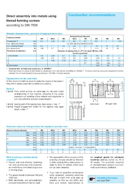
General
t1 [mm]: fillets which provide an advantage for die-cast metals
strengthening of the mandrel, centering of the screw,
prevention of buckling of the material and adaptation to
suit cost-effective standard screw lengths
t2 [mm]: bearing part of the tapping hole, taper angle max. 1° blind hole through hole
t3 [mm]: thread engagement length for the tapping hole, taper
angle max. 1°
Reference values for hole geometry into aluminium and zinc cast
Nominal thread diameter M2 M2,5 M3 M3,5 M4 M5 M6 M8
min. mm 1,85 2,33 2,84 3,31 3,74 4,72 5,66 7,61
d1
max. mm 1,91 2,39 2,90 3,39 3,82 4,80 5,74 7,69
min. mm 1,75 2,22 2,70 3,13 3,56 4,50 5,40 7,27
d2
max. mm 1,81 2,28 2,76 3,21 3,64 4,58 5,48 7,35
min. mm 1,80 2,28 2,77 3,22 3,65 4,61 5,53 7,44
d3
max. mm 1,86 2,34 2,83 3,30 3,73 4,69 5,61 7,52
t1 mm variable, minimum 1 x thread pitch p
t2 mm 4 5 6 7 8 10 12 16
t3 2 2,5 3 3,5 4 5 6 8
What should you consider during r 5IF SFQFBUBCJMJUZ PG UIF BDDVSBDZ PG UIF the required quality for automatic
assembly? screwing process should be checked machines (delivery period ca. 10 to
r 4FDVSF BOE DPTU FGGFDUJWF GBTUFOJOHT in trials using building components, in 16 weeks). The automatic assembly
can only be produced with screwdriv- order to allow for effects which have of «standard stock screws» is not nor-
ers which have controlled torque and/ not yet been detected. mally economically justifiable.
or turning angle.
r *G ZPV XBOU UP BTTFNCMF DPNQPOFOUT
r 5IF TQFFE TIPVME MJF CFUXFFO BOE using automatic screwing machines
1000 rpm. then get in touch with us as early as Calculating the torques
r #PUI FMFDUSJDBMMZ BOE QOFVNBUJDBMMZ possible, so that we can define and see page T.057
powered screwdrivers can be used. have your screws manufactured to